5. What is the surging phenomenon on a fan?
Amazing experiment!
As a child, all of us, we once discovered the surging phenomenon! The pressure, generated by our lungs blowing into a balloon, shows sometimes the difficulties to overcome the plastic resistance, till the balloon deflates suddenly in our mouth, causing the surprise for the kid and the unpleasant feeling of inverse flow direction.
In the same way, when a fan delivers pressure on a closed tank, then the flow decrease step by step as the
pressure increase in the tank. When the pressure get to the maximum fan capacity, the flow is reversing and goes back to the fan until the fan is able again to overcome the tank pressure.
Phenomenon explanation
On the chart below, at the beginning of the process, the fan generates a flow Q1 corresponding to the point 1, junction point of the curve and the resistive system. The pressure developed is equal to the dynamic pressure at outlet as the system does not own any other pressure drop. As soon as the pressure increases in the tank, the equivalent system curve straightens up and the flow starts to decrease. The curve crossing the point 2 is one of the steps of the process, till the tank pressure reaches the point 3. At that moment, the fan is not anymore able to generate a pressure higher than the pressure existing in the tank. The tank pressure becomes the system motor, generating a reverse flow in the direction of the fan. At that moment the working point of the fan goes on the point 4 with a flow at zero.
As soon as the pressure in the tank reaches the pressure at the point 4, the fan is again able to generate a
positive flow, and the working point goes up at the point 3, and so on indefinitely. This pulsating flow is called “surging”. Despite its inefficient characteristic.
As soon as the pressure in the tank reaches the pressure corresponding to point 4, the fan is again capable of generating a positive flow, and the operating point moves back up to 3, and so on indefinitely. This pulsating flow is referred to as ‘surge.’ Beyond its inefficiency in terms of the expected outcome, this phenomenon can cause concerning pulsating noise, alarming the needles of pressure gauges or ammeters. It can also cause harmful vibrations to the ducts, fan, or the fan’s supporting structure. Therefore, it is essential to strive to avoid it.
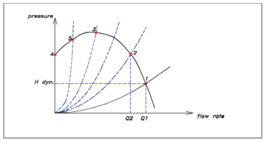
The case of a closed tank is obviously not common. In practice, the system is more or less open, and its curve is a parabola which, if it resembles the one passing through point 5, will cause surge between this point 5 and the maximum 3 on the fan curve. The magnitude of the phenomenon will be proportional to the pressure difference between points 3 and 5, while the frequency of pulsation will be related to the volume of the system (the larger it is, the more time it takes for the tank that the system constitutes to empty through the fan, and conversely, for it to raise the pressure back to its maximum). It can be demonstrated that the fan curve is unstable between points 4 and 3, and stable beyond that.
Consider point 2: this operating point is stable because to pass the flow rate Q2, it is necessary to produce a pressure that precisely corresponds to what the fan is capable of developing. If one wants to pass a flow rate higher than Q2, the system requires more pressure than the fan can provide: thus, the flow rate cannot increase.
Conversely, if one wants to reduce the flow rate, the fan is capable of developing more pressure than what is required for flow rates lower than Q2.
The fan will therefore restore the flow rate to its Q2 value, proving that point 2 is stable.
In contrast, point 5 is unstable because any attempt to increase the flow rate will be accommodated by the fan curve, capable of generating more pressure as demanded by the resistive circuit, and any attempt to decrease the flow rate will also be met by the reduction of fan pressure, corresponding to the circuit which in this case demands less pressure.
How to avoid surge?
A good fan (i.e., one with high efficiency) often has a curve that first rises and then falls. The selection of a fan corresponding to a given system will be done by choosing a fan whose curve is stable at the required operating point.
Some applications, however, require consideration of multiple operating points, some of which may fall in the surge zone. The inlet vane control is a device particularly suited for this purpose (see photo). Placed at the entrance of the fan, it has the property of degrading the fan curve by shaving off its rising part. It acts like a throttling damper would, while keeping the required operating point in a stable zone. Thus, regardless of the partial flow rate demanded corresponding to points A, B, C, or D on the resistive circuit below (graph no. 2), a particular position of the inlet vane closure will allow for maintaining a stable operating point. In contrast, to operate at QA, a damper – by consuming the pressure AA’ – would force the fan to operate at A’, thus causing surge.
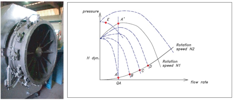
If one of the potential future operating points is at E, it is sufficient to choose a fan whose speed can be
increased (the curve shifts from N1 to N2) and then close the inlet vane control in such a way as to shave off the N2 curve. The point E will then be on a descending and stable curve.
Although energy-consuming and less elegant, another method is possible: during partial flow operation, in addition to closing the damper, one can recycle the excess flow back to the fan’s suction, or simply discharge it into the atmosphere, so that the fan operates at a constant and stable flow rate.