7. Fans in parallel
1+1 do not always equal 2
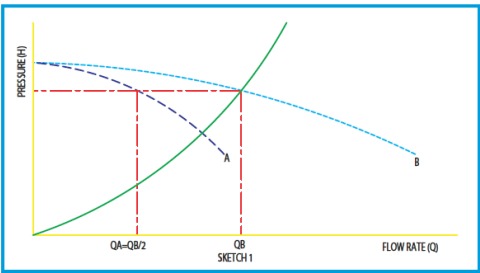
When a process requests to operate several working points, it is used to design the system on 2 fans with parallel arrangement. We can therefore stop one to complete the minimum program or to work with both when the maximum program is set on. Based on the parabola of the maximum program, we select two identical fans; each is able to ensure all the pressure and half of the requested total flow. (See chart 1: each fan owns the same A curve. Working in parallel arrangement the resulting curve B is obtained by adding each flow depending on the pressure value)
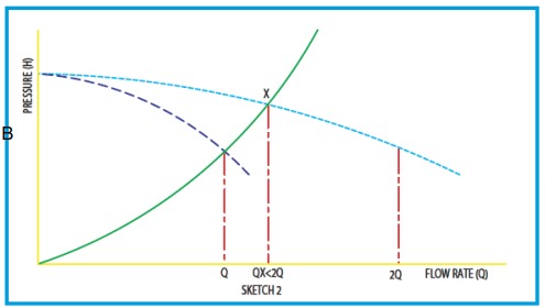
In opposite way, if in existing process we decide to double the flow on the same system, it will be vain to resolve this problem by adding a second fan identical to existing one with parallel arrangement. See chart 2: Q is the initial flow which should be brought to 2Q: if we build the resulting curve of the initial fan placed in parallel arrangement with second fan identical to existing, then we can see that it will match with the system curve at X, it means much lower than requested flow 2Q.
Other dangers with parallel arrangement
When we set fans in parallel arrangement while its curve is continuously descending, we don’t expect big
surprises taking into account what we wrote before.
In the other hand when it is question of fan with rising curve and then descending curve (it is the case with high efficiency fans) therefore the situation is different.
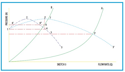
Indeed the resulting curve obtained by adding each fan flow can give different sectors curve. See chart 3: 2 fans with each the specific identical curve 1-2-3. According if we are adding 2 sectors rising 1-2, or two sectors descending 2-3, or even one sector rising 1-2 with one sector descending 2-3, we will get respectively the resulting sectors 1-2′, 2′-3′ and 2′-4.
If the resistive system is the A parabola, each fan operate at point 5 and give together the flow 5′. In the other hand, if the parabola of the system is B, it match two possible resulting curves, the arc 2′-4 and 2′-3′, at points 6 and 7, which are both possible working points. Experience shows that the fan will operate on point 6. The first fan will operate in 6″, stable operating point, while the other one will operate on 6′, in the non-stable zone of the curve.
First will work at optimal point, with good efficiency, using the large part of the available power meanwhile the second will be not useful and even may work in pumping mode, creating vibrations.
Therefore we understand that we should be carefully before using a parallel arrangement, especially when it is different fans and more when we don’t know exactly the curves system (recovered fans). In that case we may often not reach the expected result.