11. Vibration status of the fans and balancing
The fan is the origin and siege of vibrations, because of the rotating part (impeller).
For example, based on the formula F = m.w².r, an unbalance of 20 gr located at the periphery of an impeller with diameter =900mm and at 3000 RPM speed, will be generating an alternative centrifugal force of 900N. we can imagine easily that with time passing, this force is applied alternatively 50 times per second in one direction and then in the other one and will finally destruct the fan’s bearing.
The critical fans for industrial process are often equipped with vibration monitoring at the fix bearing. We can then follow the vibratory behavior of the fan with a clearer idea and during a certain time. The monitoring gives two values expressed in effective value, mm/s that we can regulate as following, according if the fan is equipped with rubber isolators or anchored directly in the concrete.

In case of operation with variable speed drive, these levels must not be surpassed in any speed level rank, and even is necessary ban the forbidden ranks (to avoid the resonance zones).
However these values will be reached only in case of uncommon problem. In normal operation, we have to control regularly the machines in order to keep the measured speeds widely below the limits.
For example, according ISO 2372, the large machines (> 300 kW) have a vibratory behavior as next:
Good: up to 1,8 mm/s
Acceptable: up to 4,5 mm/s
Still acceptable: up to 11 mm/s
Unacceptable: from de 11 mm/s.
The vibration monitoring does not give a global vibration speed value, and does not allow to define the exact reason of the vibratory phenomena. The reasons might be various:
-unbalance
-misalignment of the coupling or belting
-belts deterioration
-bearing deterioration
-particular aeraulics phenomena
-mechanical or electrical problem at the motor or variable speed drive
-etc
Establishing a spectrum according the frequencies with a sophisticated device will allow a better diagnostic, because the high peaks at specific frequencies allow in general interpreting the occurring problems.
Let’s focus on one of most important parameter in the good vibratory health state of the fan:The impeller’s balancing.
The balancing is the last stage of the impeller manufacturing. It consists in establishing the unbalance points of the impeller and the weight necessary to balance it.
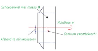
Static balancing:
This operation consists in redirecting the center of gravity of an impeller on the fan rotation axis. Practically, we redirect the center of gravity a few μm from the rotational axis.
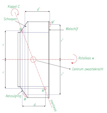
Dynamic balancing:
It allows redirecting the impeller’s main inertia axis on the rotation axis. Indeed, two unbalance items with similar mass M placed in opposition, but in two perpendicular layers to the rotational axis, are apt to give birth to centrifugal forces F=M. w².r. Despite being balanced statically, these forces will give birth to a torque equal to C=M. w².r.d); with “d” as the distance between the two layers (mentioned above).
Without dynamic balancing, it is the reaction variable forces carried on by the bearings that will balance the efforts generated, with possible dangerous vibrations as result. The dynamic balancing will allow to compensate the torque C= M. w².r.d, by another C’ torque with equal value, C’= M’. w².r’.d’.
The chosen correction layers for d’ are usually the external faces of the impeller disc and the inlet ring.
The chosen radius r’ will be preferred at the impeller’s periphery, in order to limit the balancing compensation mass. There are made with the same impeller’s material
and are usually welded.
The dynamic balancing is then as important as the impeller’s width, as for example in the case of high flow fans.
The dynamic balancing machine will allow indeed determining the mass but also the phase angle in regards to a reference point to weld the balancing weights.
The grade, notion frequently used, is a quality of impeller balancing which allows calculating the residual acceptable unbalancing, according to nominal speed when we work on the machine to be balanced. The most used ones are G 6.3 (small size machines) and G2.5 (larger machines).